NetLogoLab is the technological infrastructure that connects NetLogo and the physical world. It can be used for robotics, interactive art, scientific investigations, and model validation. This infrastructure was created at the CCL by Paulo Blikstein and Uri Wilensky in 2005 as part of the Bifocal Modeling project. For more information, please check the new and old websites, where you will find academic papers, models, and demos.
NetLogoLab is comprised of the following software and hardware components:
NetLogo's robotics/data-logging board of choice is the GoGo Board, an open-source, easy-to-build, low-cost interface designed by Arnan Sipitakiat and Paulo Blikstein, first at the MIT Media Lab, then at Northwestern's CCL, and is in continuous refinement. Other robotics hardware can be used with NetLogo, including those that are commercially available, such as Arduino boards, Vernier and Pasco sensors and actuators, Phidgets, Lego robotics kits, and VEX kits, but specific extensions have not yet been developed for each of those platforms. So far, only the GoGo Board extension is available with NetLogo's standard distribution.
The GoGo Extension for NetLogo provides primitives to communicate with a GoGo Board. This enables the user to connect NetLogo with the physical world using sensors, motors, light bulbs, LEDs, relays and other devices.
A GoGo Board is an open source, easy-to-build, low cost, general purpose serial interface board especially designed to be used in school and for educational projects. It was created by Arnan Sipitakiat and Paulo Blikstein at the MIT Media Lab in 2001, and has been actively developed since then. It is currently used in over 10 countries, such as the United States, China, Thailand, South Korea, Brazil, Portugal, Mexico, Malaysia, and Egypt.
Up to 8 sensors (i.e., temperature, light, pressure) and 4 output devices (i.e., motors, light bulbs, LEDs, relays) can be connected to the board simultaneously. The board also has a connector for add-on devices (such as displays, Bluetooth or ZigBee wireless modules, voice recorders, real-time clock, and GPS).
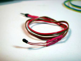
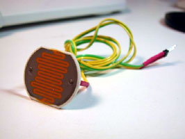
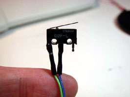
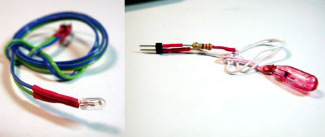
NetLogo models can interact with the physical world in two ways. First, they can gather data from the environment. This information can be used by the model to change or calibrate its behavior. This data is gathered using electronic sensors, which can measure a wide range of phenomena: temperature, light, touch (see pictures below), pH, chemical concentration, pressure, etc.
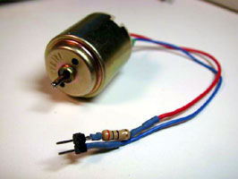
The second mode of interaction between NetLogo and the physical world is the control of output devices, or "actuators" - motors, light bulbs (see pictures below), LEDs, and more complex devices that include these outputs such as toys, remote controlled cars, electrical appliances, and automated laboratory equipment.
For educators willing to start robotics or sensing projects, there are some important considerations regarding the exact type of sensors and actuators to use - for example, the sturdiness, reliability, "openness", and cost of these devices. Both vary greatly in price and complexity. For example, for most educational projects, off-the-shelf, generic, low-cost sensors can be used with very reliable results. A generic temperature sensor with a precision of 0.5 degrees Celsius can be purchased for approximately US$ 1.00 at most sensor and electronics retailers. Using generic, low-cost sensors requires very basic knowledge of electronics. For example, some basic soldering might be needed to attach a piece of wire to the sensors. While this is feasible in schools and has been tried in several educational settings, some educators might prefer to buy proprietary sensors and actuators, which come assembled and ready to be used. Some companies offer proprietary systems for educational sensing which are more sturdy and reliable than generic sensors, but are also much more expensive. As a comparison, a proprietary temperature sensor could cost as much as US$ 50.00. Actuators follow the same rule: for example, a generic geared motor could cost from US$ 3 to 10, while a proprietary version would retail for US$ 30 or 40.
Sensors and actuators can be found through online retailers such as Digikey, Mouser, Phidgets, Spark Fun, and Solarbotics. More information about how to make sensors is available from the "How to Make Sensors" web page on the GoGo board web site.
To make use of the GoGo Board extension and the NetLogoLab framework, users need to create NetLogo models using the special primitives made available by the extension. Later in this document, we will provide examples of models that do this.
The GoGo Board is open source hardware (see the Open Hardware License here), so anyone can freely make one or even sell them. To get a GoGo Board, you have to build one yourself, ask/hire someone to do it for you, or buy from some of the existing retailers such as the SEED Foundation (or see a list here.) Many electronics assembly companies also can assemble boards, but they normally require a minimum quantity, which can range from 5 to 50. The main resource about the GoGo Board is the web site www.gogoboard.org, where you will find step-by-step instructions on how to buy components, design the printed circuit board, and assemble it - the board was especially designed to be easy and cheap to build, even if you don't have electronics skills. The GoGo Board mailing list is gogoboard@yahoogroups.com, and you can join it by going to Yahoo groups.
The GoGo Board connects with the computer via the USB port (older versions used the serial port which required a USB-to-Serial adapter -- one model that worked quite well was the Keyspan USA-19HS). To connect, make sure to plug the USB cable into the computer. Turn the GoGo Board on using the switch behind the power connector: the board will beep twice and the red light will turn on.
The GoGo extension requires no special installation on Mac OS X. The only issue for now, due to a bug in the open source software we use for controlling the serial port, is that you CANNOT use the "gogo:close" command, or execute the "gogo:open" twice. This will be fixed as soon as we get the updated software from the RXTX team. If you are using any of the example models (GoGo Monitor and GoGo Monitor Simple), DO NOT click on "setup" twice -- click once and wait some seconds for the connection to be made.
Many versions of Linux require no special installation. However, if
you face problems, ensure that you are able to write to the serial
devices (usually, this means /dev/ttyS*). In most Linux
distributions this can be set up through the User Manager.
The GoGo Extension comes preinstalled when you download and install NetLogo. To use the extension in your model, add this line to the top of your Code tab:
extensions [gogo]
If your model already uses other extensions, then it already has an
extensions line in
it, so just add gogo to the list.
After loading the extension, see what ports are available by typing the following into the command center:
print gogo:ports
You can open the serial port that the GoGo Board is connected to so
that commands can begin to be sent to the board by using the
gogo:open command.
To make sure the board is properly connected, check that it is
responding with the ping reporter. Note that in
order to communicate with the board, you need to know which
communications port it is connected to. If you are not sure which
port is being used, you can use the gogo:ports primitive (see
below), or you can find out by using the Device Manager on a Windows
computer (in the Control Panel, click on the System icon), or the
System Profiler on Mac OS X.
On Windows:
gogo:open "COM1"
print gogo:ping
On Linux:
gogo:open "/dev/ttyS01"
print gogo:ping
On Mac:
gogo:open "/dev/tty.KeySerial1"
print gogo:ping
For more information on NetLogo extensions, see the Extensions Guide.
For examples that use the GoGo extension, see the Robotics/NetLogoLab section under Sample Models in NetLogo's Models Library.
The first step when creating a NetLogoLab model is to add the
extensions keyword
to NetLogo's Code tab. Just go to the Code tab and add this line:
extensions [gogo]
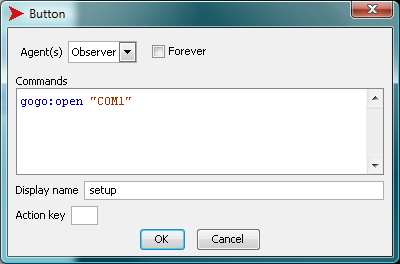
The second step is to create a button to connect NetLogo to the GoGo board using the correct serial port for your operating system as described above.
gogo:open "COM1" ;; (for Windows machines)
When you are done creating the button, the "edit" dialog should look like this:
Now let's actually start the model. Imagine that we want to control a car with four wheels and two motors attached to the back wheels. We will assume that you have built such as car and connected the motors to the output ports "a" and "b" on the GoGo board. One very simple approach could be to create two buttons for each motor, "on" and "off":
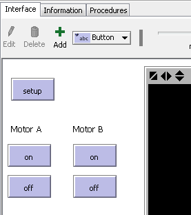
The code associated with these buttons is very simple: for the "on" button, we could simply have
gogo:talk-to-output-ports ["a"]
gogo:output-port-on
For the off button, it would be very similar:
gogo:talk-to-output-ports ["a"]
gogo:output-port-off
The other set of "on" and "off" buttons, used to control the second motor, would have very similar code, except that we would use the second output port ("b"), so:
gogo:talk-to-output-ports ["b"]
We could make our model more interesting by adding a "toggle direction" button, adding a button with the following code, which would reverse the direction of motors "a" and "b":
gogo:talk-to-output-ports ["a" "b"]
gogo:output-port-reverse
To create a simple sensing project, we will assume that you have added the GoGo extension to your model and successfully opened a connection to the GoGo board, i.e., adding the "extensions" command to the Code Tab and adding a "setup" button as previously described. For this sensing project we do not need motors, but we will need another device: a temperature sensor (click to see more information about a typical temperature sensor at Digikey's web site). Instructions on how to purchase and assemble a temperature sensor can be found in the "Making Sensors" tutorial on the GoGo Board's web site. This is how a temperature sensor will look after it has been assembled:
The simplest use of a temperature sensor, obviously, is to display the temperature. We could achieve this by adding a monitor to the NetLogo interface with this code:
gogo:sensor 1
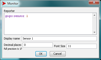
The sensor values shown are arbitrary numbers within a given range, and need to be properly converted to actual temperature units such as degrees Celsius or Fahrenheit. For all sensors, the GoGo Board's reporting range is from 0 to 1023. Every sensor comes with a data sheet with a converting formula or table that will transform the arbitrary 0-1023 range into an actual physical unit. Let us imagine that the sensor's data sheet contains a conversion formula that looks like this: degrees = arbitrary value / 30. The monitor on the NetLogo interface could be changed to:
gogo:sensor 1 / 30
The sensor value could also be used to control on-screen objects, such as turtles. For example, let us create two buttons: a "create one turtle" button, which will clear the world and create a turtle, and a "move with heat" button, that will cause the turtle to move forwards depending on the temperature reading from the sensor. The code would look like this:
to create-one-turtle
  clear-all
  create-turtle
end

to move-with-heat
  if gogo:sensor 1 < 500
    [ forward 1 ]
end
If the "move with heat" forever button is activated and the user heats up the sensor (by rubbing it, or slowly bringing a flame near it), the heat threshold will be achieved (< 500) and the turtle will move. (Note that we are using one kind of temperature sensor for which resistance decreases with temperature, and so the sensor readings will go down as we heat the sensor up. This is a very common and inexpensive off-the-shelf sensor).
A more elaborate use of this sensor apparatus would be to control output devices, such as motors. The user could, for example, turn a motor on when the value from the temperature sensor reaches 500, using the following code:
to turn-motor-on-with-heat
  if gogo:sensor 1 < 500
  [
    gogo:talk-to-output-ports ["a"]
    gogo:output-port-on
  ]
end
Another possible use of the sensing primitives is to plot and log data. Logging could be useful for more elaborate data analysis and comparison, and can be achieved with NetLogo's list commands. For example, if the user wants to log sensor values from sensor 1 every 0.5 seconds, the code could look like this:
to log-data-from-sensor
  set data-vector lput (gogo:sensor 1) data-vector
  wait 0.5
end
Finally, plotting data is straightforward. The following code, for example, would create a graph for the value of sensor 1:
plot (gogo:sensor 1)
For more information on the GoGo Board's extensions functionalities and primitives, please refer to these two sample models: GoGoMonitor.nlogo and GoGoMonitorSimple.nlogo.
gogo:beep gogo:burst-value gogo:close gogo:install gogo:led-off gogo:led-on gogo:open gogo:open? gogo:ports gogo:output-port-coast gogo:output-port-off gogo:output-port-reverse gogo:output-port-[that|this]way gogo:ping gogo:sensor gogo:set-burst-mode gogo:set-output-port-power gogo:set-servo gogo:stop-burst-mode gogo:talk-to-output-ports
Sends a signal to the GoGo Board to make it emit an audible beep. Useful for a testing purposes.
Example:
gogo:beep
Reads the most recent value that was received by the gogo board from a sensor set to send burst data.
See also gogo:set-burst-mode and gogo:stop-burst-mode.
If on a Windows system, attempt to force-run the Windows driver installer.
Example:
gogo:install
Sends the signal to the GoGo Board to turn off the LED.
Example:
gogo:led-off
See also gogo:led-on.
Sends the signal to the GoGo Board to turn on the LED.
Example:
gogo:led-on
See also gogo:led-off.
Open a connection to the GoGo Board connected to serial port named
port-name. See gogo:ports
for more information about port names.
If the GoGo Board is not responding, or you attempt to open a port without a GoGo Board connected to it, an error will be generated.
Example:
gogo:open "COM1"
See also gogo:open? and gogo:close.
Reports true if there is a connection to a GoGo Board open. Reports false otherwise.
Reports a list of serial port names that a GoGo Board may be connected to. On certain computers, you might get a list of two or three different serial ports. In that case, try to open each of them until the connection is successful.
Turns off the power of the active ports. When attached to motors,
does not apply a braking force as gogo:output-port-off does.
Therefore, the motor will gradually slow down before stopping
completely. This will have the same effect as gogo:output-port-off on most
output devices other than motors. The output-ports affected by this
command are determined by the gogo:talk-to-output-ports
command.
The following code will turn on an output port a for 1 second, and then stop the motor gradually:
gogo:talk-to-output-ports ["a"]
gogo:output-port-on
wait 1
gogo:output-port-coast
Turns off power to the output ports. If using motors, a braking force
is applied. The output ports affected by this command are determined
by the gogo:talk-to-output-ports
command.
Turns on power to the output ports. The output ports affected by this
command are determined by the gogo:talk-to-output-ports
command.
Reverses the direction of the output ports. The output ports affected
by this command are determined by the gogo:talk-to-output-ports
command.
Apply power to the output port in a given direction. Output ports can
be powered in two directions, arbitrarily called thisway and
thatway. The output-ports affected by the command are
determined by the gogo:talk-to-output-ports
command. Note that this is different from gogo:output-port-reverse
because thisway and thatway will always be the same
direction provided the connector's polarity is the same.
This command will set the corresponding output ports as active. They
will be the ones affected by the commands such as gogo:output-port-on and gogo:output-port-off. The user
can "talk" to one or multiple ports at the same time.
Output ports are typically connected to motors, but you could also
use bulbs, LEDs and relays. Output ports are identified by one letter
names: "a", "b", "c", and
"d".
Examples:
;; talk to all output-ports
gogo:talk-to-output-ports [ "a" "b" "c" "d" ]
;; will give power to all output-ports
gogo:output-port-on

;; talk to output-ports A and D
gogo:talk-to-output-ports [ "a" "d" ]
;; will turn off output-ports A and D.
;; The other output-ports will keep
;; their current state
gogo:output-port-off

gogo:talk-to-output-ports [ "c" "b" ]
;; turn off remaining output-ports
gogo:output-port-off
Checks the status of GoGo board. This is mostly used to make sure the board is connected to the correct serial port. It reports true if the GoGo Board responds to a diagnostic message, and false otherwise.
Example:
print gogo:ping
Reports the numeric value of the sensor named sensor. Sensors are identified by numbers 1 to 8. Values range between 0-1023. 1023 is returned when there is no sensor attached to the port (highest resistance), or when the sensor is an "open" state. Zero is returned when the sensor is short circuited (no resistance).
Examples:
print gogo:sensor 1
;; prints the value of sensor 1

foreach [ 1 2 3 4 5 6 7 8 ]
  [print (word "Sensor " ? " = " gogo:sensor ?)]
;; prints the value of all sensors

if gogo:sensor 1 < 500 [ ask turtles [ fd 10 ]]
;; will move all turtles 10 steps forward if sensor 1's value is less than 500.

loop [if gogo:sensor 1 < 500 [ ask turtles [ fd 10 ] ] ]
;; will continuously check sensor 1's value and
;; move all turtles 10 steps forward every time
;; that the sensor value is less than 500.
Turns on "burst mode" for the sensors in
sensor-list. If high-speed-mode? is true
then high speed burst mode will be used. If it is false, then low
speed burst mode will be used.
See also gogo:burst-value and gogo:stop-burst-mode.
Examples:
  gogo:set-burst-mode [ 1 2 3 ] true
  ;; turns on high speed burst mode for sensors 1, 2 and 3

  gogo:set-burst-mode [ 4 ] false
  ;; turns on low speed burst mode for sensor 4
  ;; this will also override any previous set-burst-mode calls
  ;; so there will be no new burst mode data for sensors 1, 2 and 3
Sets the power level of the active output ports. power-level
is a number between 0 (off) and 7 (full-power). The output-ports
affected by this command are determined by the gogo:talk-to-output-ports
command. Note that for many practical applications it is more
efficient to use mechanical devices, such as gears and pulleys, to
control the torque of motors.
Example:
gogo:talk-to-motors ["a" "b" "c" "d"]
gogo:set-motor-power 4
;; will lower the power of all output ports by half of the full power .
Set the servo position to the value given by servo-position.
servo-position must be between 20 and 40 (inclusive).
Example:
gogo:set-servo 25
Turns off "burst mode" for all sensors
See also gogo:burst-value and gogo:set-burst-mode.