404 Not Found
The page you are looking for might have been removed, had its name changed, or is temporarily unavailable.
|
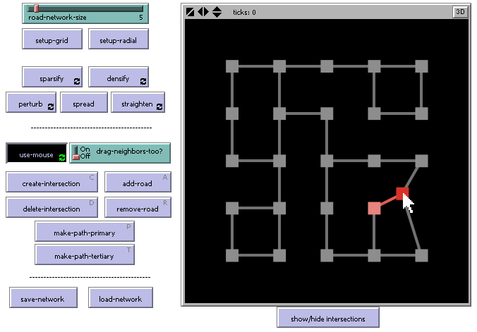
An interactive applet version of the Road Network Builder model can be found in the bottom half of this page, along with documentation about how to use the model. However, before jumping into the interactive demonstration, we offer a quick tour of some of the more important features/concepts. | ||
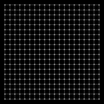
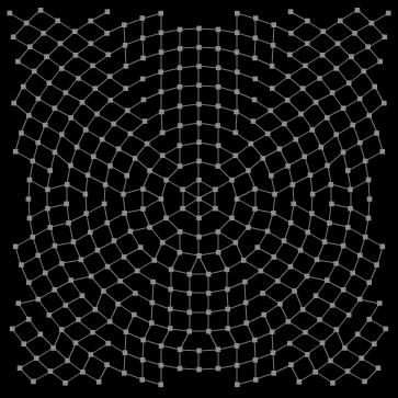
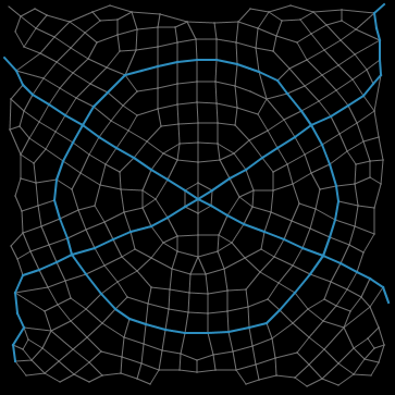
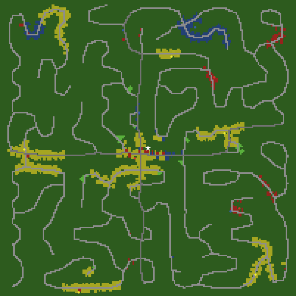
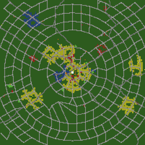
There are two basic initial layout patterns for the road network -- a gridded layout (shown on the left) and a radial layout (shown on the right). The radial layout road network structure was previously unsupported by the Cities CORE model, until the advent of this extension. | ||
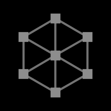
The size of the network can vary widely, from the simple small-scale network (on the left) with just 12 road segments to large-scale networks with thousands of road segments (on the right). | ||
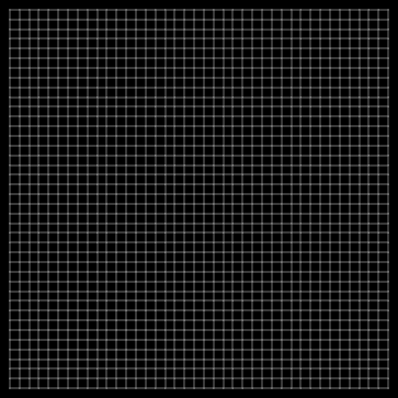
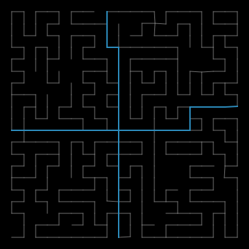
The Road Network Builder extension model includes a special tool for making the whole network more sparse (as on the left), or more dense (as on the right). The Cities CORE simulator model supports two designations for roads -- primary roads and tertiary roads. This extension allows you to specify which roads in the network should be primary. Primary roads are thicker, and shown in blue. | ||
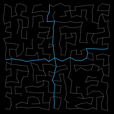
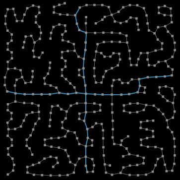
Both of the networks shown above have the same road connections as the sparse grid-layout example given on the left above. The network on the left has been manipulated with the perturbation tool, to give it a nightmarish slanted off-kilter look and feel. The network on the right was manipulated with the spreading-tool, which pushes and pulls roads in a fashion that often creates natural looking winding streets and courts. Notice that the road intersection nodes can be either hidden (as on the left) or visible (as on the right). | ||
Automated tools that manipulate the whole network at once are a great way to quickly create a certain style of road network. However, if you have very specific ideas about the type of road network you want to build, or there's one road segment that "sticks out funny", then you need to have full manual control over the network being built. The Road Network Builder provides users with this level of freedom. Roads may be manipulated by moving, creating or deleting "road intersection nodes", or by adding or removing roads between these nodes. | ||
After the road network has been satisfactorily created, it can be brought to life by using the Cities CORE simulator. First use the "save-network" button in the Road Network Builder model, and call the creation something like "myroads.network". Then open the Cities model, click the "import-network" button, locate "myroads.network", and the road network will be brought in. Run the Cities model by clicking GO, and the developers will start to build near your roadways. (Note that if you have any road developer agents, they are likelyto build additional roads of their own choosing!) | ||
Applet DemoBecause of security restrictions imposed on Java applets running inside web browsers, the "save-network" and "load-network" features of the model are not available. To use these, please download the model and run it using NetLogo (version 4 or later). The applet (below) requires Java 1.4.1 or higher. It will not run on Windows 95 or Mac OS 8 or 9. Mac users must have OS X 10.2.6 or higher and use a browser that supports Java 1.4. (Safari works, IE does not.) On other operating systems, you may obtain the latest Java plugin from Sun's Java site.
Download this model file, and use Road Network Builder.nlogo WHAT IS IT?This model is a flexible design tool for creating road networks that may be imported into the CITIES model, which simulates urban growth and land usage patterns. The CITIES model is capable of growing its own sophisticated road networks, in a rather organic fashion, by having road-builder agents wander the map and create roads where it would be logical to do so. However, sometimes it is desirable to have more fine-grained control over the road network structure within a city, and this Road Network Builder model serves this purpose. HOW IT WORKSA road network is defined by some number of road "intersections", which have physical locations in the world. These intersection nodes may be connected to other interseciton nodes by roads, which are straight line segments between nodes. Note, however, that a curvy section of road may be simulated by stringing together several intersection nodes that each have only two roads going out of them. The intersection nodes can be repositioned either by using automated tools (such as the PERTURB or STRAIGHTEN buttons), or by manually adjusting single nodes using mouse interaction. Road segments may be designated either primary or tertiary. Primary roads appear thicker in the visual display, and colored sky blue, rather than gray. The networks that are created can be saved, and re-loaded for further editing at a future date. The saved road networks can also be imported into the CITIES model. HOW TO USE ITThere are two basic setup patterns for the road network included in this model (though it could be extended to have others). These are a grid pattern (initiated by the SETUP-GRID button) and a radial hub pattern (initiated by the SETUP-RADIAL button). The size of the road network is controlled by the ROAD-NETWORK-SIZE slider. In both patterns, initially all roads are marked as tertiary. If you wish to have primary roads, you must manually mark them using mouse interaction. There are several functions that work on the network as a whole. The PERTURB button causes all of the intersections to jitter randomly. The STRAIGHTEN button causes all of the intersections to move back toward their original locations. Some important notes: 1) when nodes are moved manually, the locations they were moved to is considered to be their "original location" 2) when a road network is loaded from a file, the loaded locations are considered to be the original locations. The SPARSIFY button removes roads randomly from the network, resulting in a more sparse road network. SPARSIFY will never remove a road that would cause an intersection to become a dead-end -- if you want to do this, you must manually do it with the USE-MOUSE mode. Also, SPARSIFY will never remove road segments that are marked as primary. Conversely, the DENSIFY button randomly adds more roads to the road network. Roads are only added in ways that do not create underpasses/overpasses (i.e. line edge intersections) with existing roads. The SPREAD button uses a visual graph layout algorithm called "spring layout" that pushes and pulls the intersection nodes as if there were coiled springs in place of the road edges. Also, all nodes repel all other nodes, to keep them from getting too close to each other. This often results in smooth and rather pleasing road network formations. A single click of this button moves the nodes a little bit in the direction of the forces acting on them. To manually interact with individual roads and intersections, click down the USE-MOUSE button to turn on mouse interaction. Note that several of the buttons that you can use to interact with the network (DELETE-INTERSECTION, CREATE-INTERSECTION, REMOVE-ROAD, ADD-ROAD, MAKE-PATH-PRIMARY, MAKE-PATH-TERTIARY) have keyboard shortcut keys that you can use (shown in the When USE-MOUSE is turned on, you can click and drag intersection nodes to new locations. If DRAG-NEIGHBORS-TOO? switch is turned ON, then the nodes that are connected to the node being dragged are also repositioned. The most recently selected node is colored red, and the second most recently selected node is colored pink. The DELETE-INTERSECTION button will remove the most recently selected node (the red node), as well as any road segments that connect to it. The CREATE-INTERSECTION button will create a new intersection node (with no road segments attached to it) somewhere in the world view. If the mouse cursor is currently positioned inside the world view (which is possible, if you are using the shortcut keys), the new node will appear at the current mouse location. Otherwise, the location of the new node on the map is somewhat unpredictable. The new node will beceom the "most recently selected" node, and will be colored red. The REMOVE-ROAD button removes the road segment (if one exists) between the two most recently selected intersection nodes (the red and pink nodes). The ADD-ROAD button adds a road segment between the two most recently selected intersection nodes, if one does not already exist. The MAKE-PATH-PRIMARY button selects a (shortest) path between the two most recently selected nodes (this path may consists of numerous segments, if the two nodes are not adjacent to each other in the network), and changes every road segment on this path to a primary road segment. If there is no path in the network between the selected nodes, then nothing happens. The MAKE-PATH-TERTIARY button selects a (shortest) path between the two most recently selected nodes. This path must consist only of primary road segments. If such a path does not exist, then nothing happens. The SAVE-NETWORK button allows you to save your current road network as a file. You will be prompted to choose a file name. (It is recommended, though not necessary, that you give the file a meaningful extensions, such as "xxxxx.network".) The LOAD-NETWORK button allows you to load a previously saved road network file. The "SHOW/HIDE INTERSECTIONS" button toggles whether the intersection nodes are displayed in the world view. Temporarily hiding the nodes can give a better idea of what the road network actually looks like. EXTENDING THE MODELA simple extension to this model would be to include another basic setup pattern (like SETUP-GRID and SETUP-RADIAL). Start by reading the code for the SETUP-GRID and SETUP-RADIAL procedures, and then design your own. You may or ma not need to make modifications to the FINISH-SETUP procedure. Another extension to this model would be to support curvy roads more directly, by changing the link shapes of the roads to a more curvy link shape (see the Link Shapes Editor, under the Tools menu). In order for this change to also be reflected in the CITIES model, you would need to make changes to the file "import-road-network.nls", to have the turtles that create the road network move in curved patterns on their way to their destination. NETLOGO FEATURESThis model makes considerable use of the NetLogo's support for the links agent type. It uses two different link breeds (one for primary roads, and one for tertiary roads). It also makes use of one undocumented NetLogo primitive called __network-shortest-path-links, for the convenience of turning a whole path of road primary or tertiary with one click. The functionality provided by this primitive will likely be officially supported and documented in some future release of NetLogo. RELATED MODELSThis model is a companion model, or extension, to the "Cities" model. For other models that investigate topics related to urban development, see the "Urban Suite" models. This model is a highly network-based model, and is thus related to several of the Network models in the Models Library, such as Preferential Attachment and Giant Component. CREDITS AND REFERENCESThis model was written by Forrest Sondahl in 2007, as a tool for developing transportation network structures that could be integrated into the Cities model. Back to the Main Cities Project Web Site. |
The page you are looking for might have been removed, had its name changed, or is temporarily unavailable.
The Center for Connected Learning and Computer-Based Modeling
Annenberg Hall Rm 225, 2120 Campus Drive, Evanston IL, 60208
Phone: 847-467-7593 | Fax: 847-491-8999| Email: ccl-website@ccl.northwestern.edu
Affiliated with: Learning Sciences Department,
Computer Science Department,
and The Northwestern Institute on Complex Systems